Skip to content
← All projects

Project / Hardware

FSAE Electric — Precharge & Protection PCB

Role
Hardware design
Timeline
2025 – 2026
Team
BU Racing — FSAE Electric
Tools
Altium LTspice MATLAB

At a glance

Problem
Charging a 298.2 V (max) / 255.6 V (nom) accumulator directly into discharged motor-controller capacitors causes destructive inrush current — the precharge circuit must ramp bus voltage safely before the main contactors close.
Approach
Designed a precharge and protection PCB in Altium: current-limited ramp through a power resistor, voltage monitoring to detect completion, and hardware interlocks to block main contactor closure until the bus is within threshold.
Outcome
Board passed bring-up and bench validation; integrated into the 2026 competition vehicle accumulator.
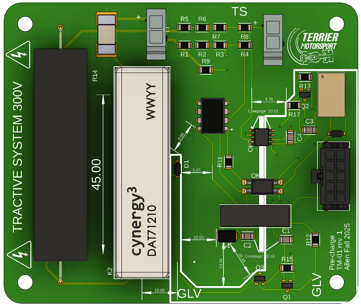
Assembled precharge PCB, top side
Fig. 1 — Assembled precharge & protection PCB.

Overview

As you may know, I'm a part of Terrier Motorsports. We build an electric race car and compete with other schools at the Formula Hybrid + Electric competition in New Hampshire each year, and hopefully at FSAE in Michigan, too, in the future. We're a pretty new team, which means having to figure out a lot of stuff on my own. This makes designing boards challenging, but super fun.

As a club, we've never actually gotten a car to drive at competition yet, so we're hoping to get this years car, TM-01, fully operational at New Hampshire.

I'm part of the Grounded Low Voltage team, which means I design parts of the electrical safety hierarchy we call the "Shutdown Loop." It ensures that the vehicle only turns on if everything is working correctly or shuts down if anything starts behaving abnormally. Last year, I worked mainly on board assembly, testing, and wiring harness routing, but this year I've leaped into a more design-focused role.

Design decisions

Previously, we used a 555 timer which is no longer permitted, and the board exclusively used through-hole components. In the new design, we not only transitioned to discrete voltage measurement using the LM393 comparator chip, but we also started using mostly surface-mount components. Although sizing down isn't a priority right now, it's good preparation for our next car, TM-02.

Since we are measuring directly from the HV sides now, there are strict rules for HV and LV isolation that we need to consider. The slot in the board is for meeting PCB on-surface creepage distance requirements. The components that go over the slot are the optocouplers and a galvanically isolated DC-DC converter.
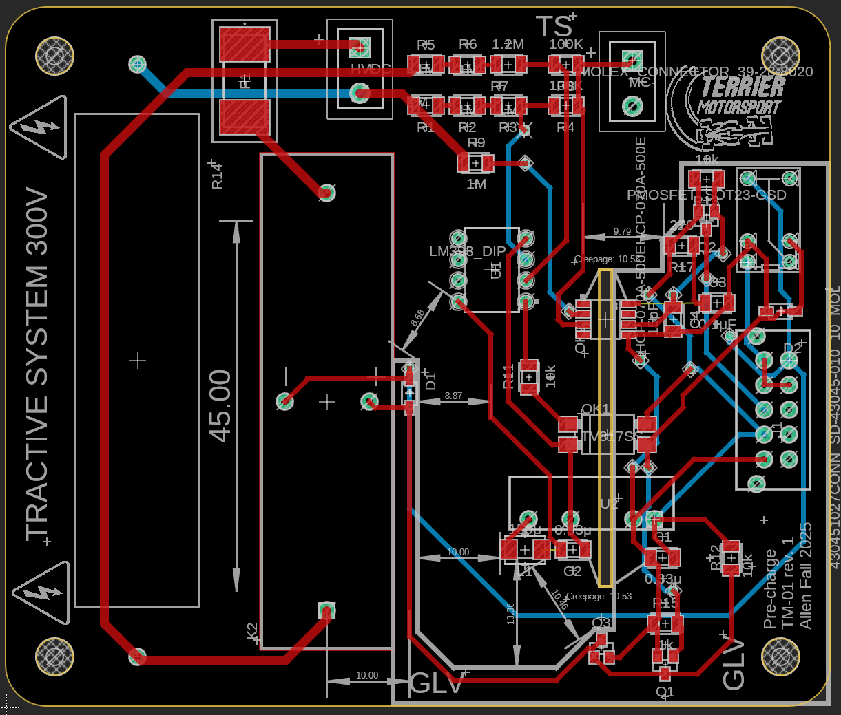
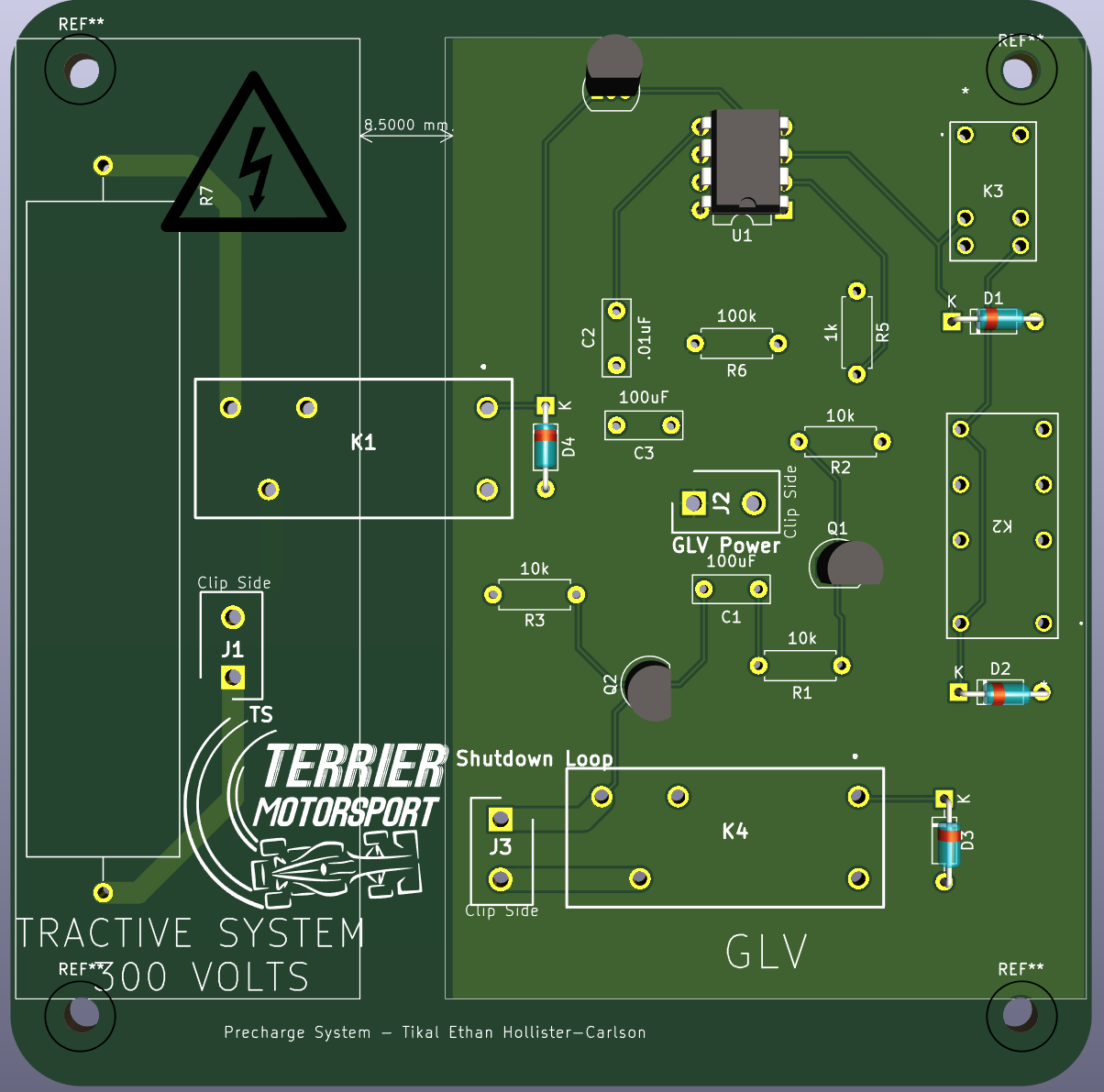
PCB layout — precharge board
Fig. 2 — PCB layout, precharge board.
Earlier revision of the precharge board
Fig. 3 — Previous revision, for comparison.
Technical details
Parameter Value Notes
Pack voltage (nom.) 255.6 VDC
Pack voltage (max.) 298.2 VDC
Precharge threshold 93.9% Vacc LM358 comparator
Precharge resistor 5 kΩ equiv. Two SQP25AJB-10K in parallel
Resistor power 25 W / 156.25 W (5 s) 1000 V rating
MC discharge R 188 kΩ Included in timing
Precharge relay Sensata DAT71210 SPST, 3 A, 7000 Vdc
Comparator IC LM358 ~9 V at threshold
Optocoupler LTV-817S Closes shutdown loop relay
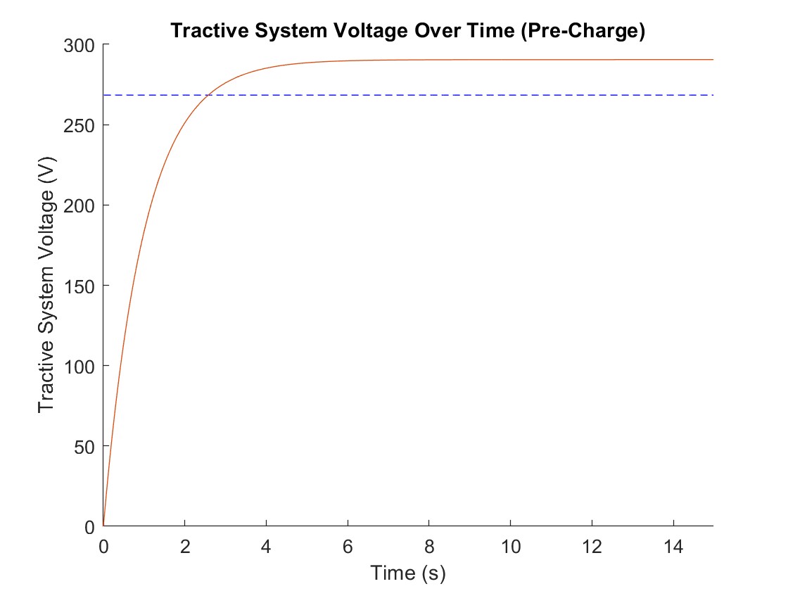
Precharge time See calculations
HV connectors Molex 39-28-8020 J1: MC+/ACC+; J2: MC−
LV connectors Molex 43045-1027 GLV-to-GLV signals
Simulation graphs
TS voltage vs. time
TS voltage vs. time
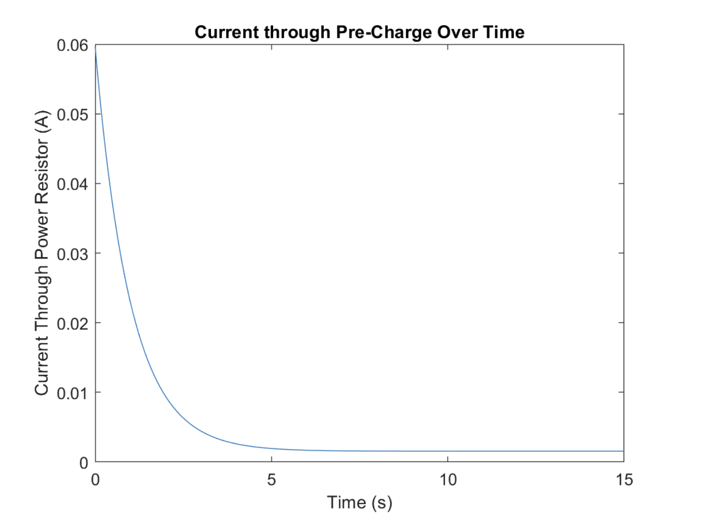
Current vs. time
Current vs. time
Resistor power vs. time
Calculations

Voltage Division

Reference voltage across the 100 kΩ resistor:

$$V_{ref} = 300 \cdot \frac{0.1}{3.3} = 9.09\text{ V}$$

Comparator Threshold

Comparator outputs high when $V_{in} > V_{ref}$:

$$V_{MC} = 9.09 \cdot \frac{3.1}{0.1} = 281.79\text{ V} = 93.9\%$$

Pre-charge Timing

$\tau = 10\text{ k}\Omega \cdot 200\text{ }\mu\text{F} = 2\text{ s}$

$$281.79 = 300\!\left(1 - e^{-t/2}\right) \implies t \approx 5.60\text{ s}$$

Power Dissipation

$$I = \frac{300}{3.1\text{ M}\Omega} = 0.0978\text{ mA}$$ $$P_{R1} \approx 0.009\text{ W},\quad P_{R2} \approx 0.0009\text{ W}$$

¼ W rated resistors are sufficient.